Flashing
Flashing a microcontroller is fairly straight forward. There are two methods in doing so: JTAG and over serial. Often times, things are flashed over JTAG first and the devices are flashed over serial after that. This page describes how to do both methods.
Flashing over JTAG
Flashing a microcontroller over JTAG is fairly straight forward if you are using a JLink programmer or the on-board JLink microcontroller on a devkit. However, not all devkits come with the means to flash a microcontroller over JTAG easily. This section will describe how to program a microcontroller over JTAG using the nRF52840 DK. These instructions can also be applied to other Nordic development kits.
Getting the devkit ready
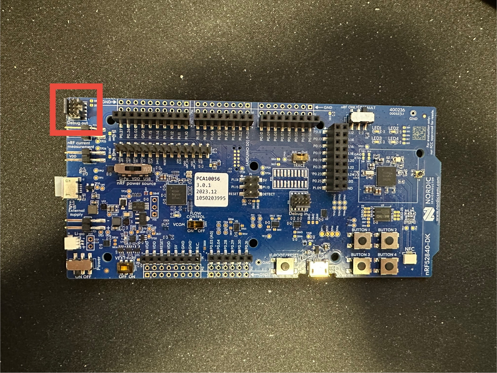
The devkit has 3 JTAG ports. There is the one that is connected to the evaluation microcontroller and is inaccessible. The second port is connected to a "Debug Out" header in the corner of the board (you may have to look for it if using different dev kit). If using the second port, just connect your cable and you are done.
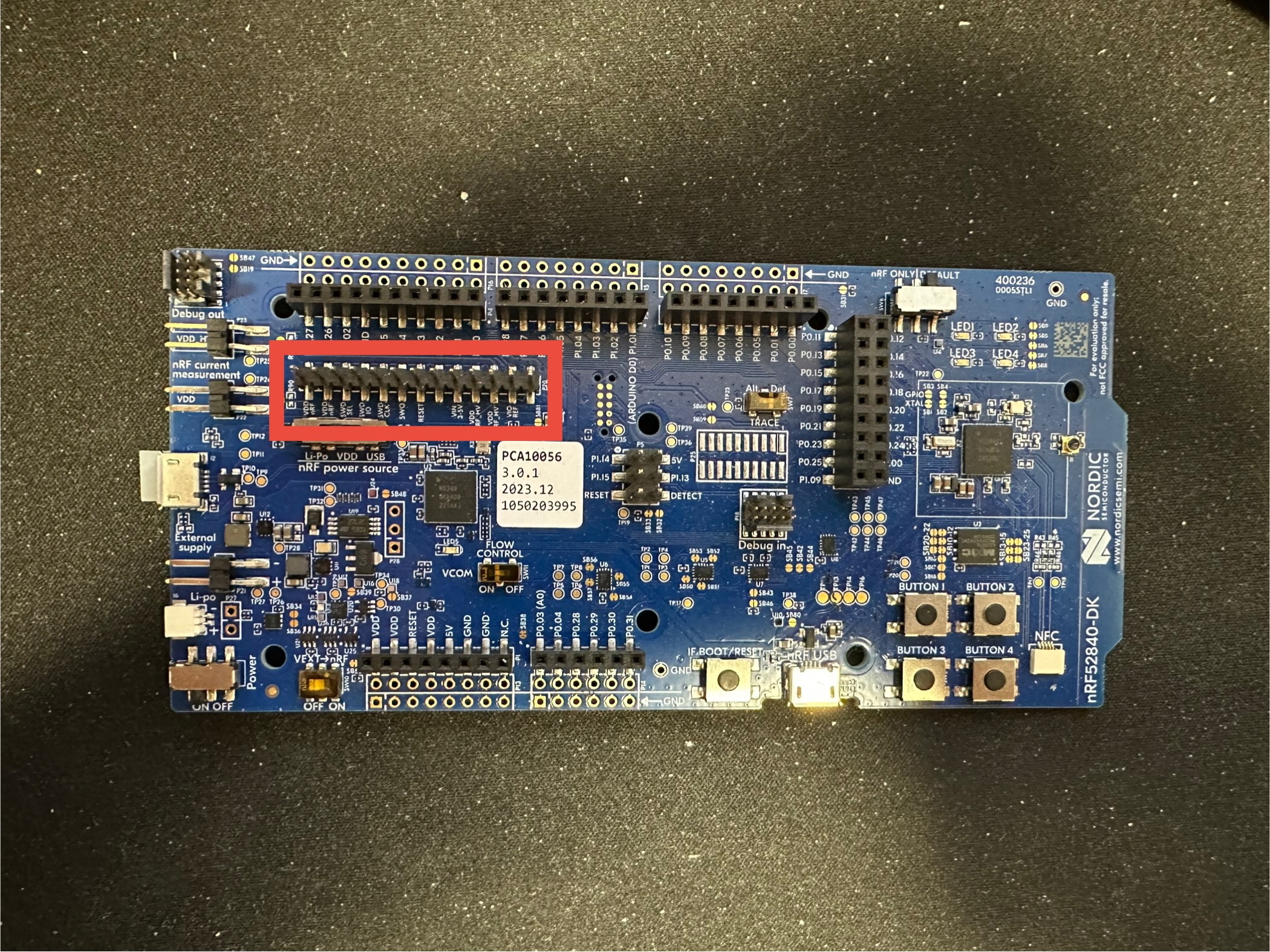
The third port are normal headers that jumper wires can be connected to. In order to use this port, the SWD SEL
needs to be tied to VDD nRF. This will disable port 2, but enable port 3.
Flashing
After getting things set up on the hardware, things should be easy to flash over JTAG.
If you are using VS code, all you have to do is press the "Flash" button and select the devkit to flash to (usually something like nRF52840 DK).
If you are using the CLI, you want to run the following commands:
For flashing a microcontroller with an image downloaded from GitHub releases, it is recommended to use this method.
- Open desktop application
- Open the "Programmer" app
- Press "Select Device" and select the nRF devkit
- Press "Add file" and add "merged.hex"
- Press "Erase & Write"
Flashing over USB
The other method for flashing is over USB and is used for upgrading the firmware. To flash the microcontroller over USB, it is recommended that the Device Firmware Upgrade API is used in the serial driver. a few basic steps just need to be followed:
- Find the correct USB port used for DFU.
- Create a new
AresDfuinstance. - Upload the signed hex file to the microcontroller.
- Reset the microcontroller (it should take a few seconds to swap images).
- Test the image to make sure things are not crashing.
- Confirm the image.
Below is an example program:
from pathlib import Path
from ares_lora import AresDfu, find_ports, LoraSerial, LoraSerialConfig

image_path = "build/.../zephyr.signed.bin"

def find_dfu_port() -> Path:
    ports = find_ports()
    for product in ports:
        for port in ports[product]:
            config = LoraSerialConfig(port)
            with LoraSerial(config) as s:
                try:
                    s.version()
                except TimeoutError:
                    return Path(port)
    raise IOError("No DFU port found")

# Upload the image and run the image
port = find_dfu_port()
dfu = AresDfu(port, verbose=True)
dfu.upload(image_path)
dfu.reset_mcu(True)

# Confirm the image
input("Press enter to confirm image...")
# Ports may have changed...
port = find_dfu_port()
dfu = AresDfu(port)
dfu.confirm_image()